weight of rigid flex boards
Rigid flex circuit boards are hybrid PCBs that combine rigid stability with flexible sections to enable bending and folding. They are used in a wide range of electronic devices to improve functionality, reduce cost, and increase reliability. Rigid flex technology is especially well suited to applications that require flexibility, durability and space savings, such as medical imaging equipment and military missile guidance systems, but also in consumer electronics like laptop computers and wearables.
The process of designing a rigid flex board begins with creating a digital representation using CAD software, which is then transformed into manufacturing files. During the design phase, it is important to consider a variety of factors, such as the material types and thicknesses, which are determined by the intended operating environment. It is also critical to ensure that the rigid and flexible sections will be able to withstand mechanical stress, temperature variations and moisture, as well as any chemical exposure.
Once the PCB design has been completed, it is time to select a manufacturer. When choosing a manufacturer, it is important to consider their experience, quality, manufacturing capabilities and customer support. It is also helpful to request references from current and previous customers, as this will provide valuable insights into a manufacturer’s ability to meet or exceed customer expectations, and their level of customer satisfaction.
How does the weight of rigid flex boards compare to traditional PCBs?
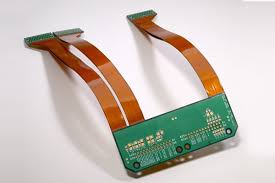
Rigid flex boards are built in a similar manner to traditional rigid PCBs, with the exception that there are plated through holes (PTH) included on both sides of the circuit board. This allows for seamless integration of both rigid and flexible sections and eliminates the need for additional connector components, resulting in a much simpler assembly process. It is also possible to incorporate integrated ZIF contacts for easy modular interconnects, further simplifying the assembly and test process.
In addition to reducing assembly costs, rigid flex PCBs can also reduce overall package size and weight. This is due to the fact that the conductive traces are much thinner than in a conventional PCB, allowing them to be positioned more closely together and therefore resulting in a lower weight. This is particularly beneficial in high shock and vibration environments, where the reduced mass of the flex circuit can significantly reduce the overall system weight.
For complex designs with many signal layers and a tight bend radius, it is recommended to use patterned copper rather than solid copper pours. This will allow the flex to retain some flexibility, without compromising the integrity of the signal layers. In addition, incorporating S curves on the flex region can help reduce the risk of cracking or breaking during bending. Adding a hashed ground plane layer can further assist with maintaining flexibility and a tight bend radius.